Float voltage is an easy setting to get wrong — and when misconfigured it quietly shortens pack life, causes chronic imbalance, and produces intermittent BMS trips that waste troubleshooting hours. Unlike lead-acid chemistry, LiFePO₄ (LFP) cells have different electrochemical needs: they tolerate full charge differently, they don’t suffer sulfation, and they respond badly to unnecessary prolonged top-end charging. This article gives engineers and system integrators a clear, practical methodology for choosing float, absorption, and storage voltages for 12 V, 24 V and 48 V LFP systems, shows how BMS behavior affects float strategies, and gives actionable steps for tuning chargers and energy systems to maximize life and availability.
What “float” really means for LiFePO₄ — and why it’s not the same as lead-acid
Float voltage is the voltage a charger maintains after the battery has reached “full” to overcome self-discharge and keep the battery at readiness. For lead-acid systems that prevents sulfation; for LiFePO₄ it is rarely required as a continuous maintenance strategy. In many LFP installations the best practice is to stop charging at a correct absorption voltage and let the BMS or the natural self-discharge determine when a controlled top-up is needed, rather than holding the battery at a constant float that keeps cells permanently at 100%. Modern BMS units may intentionally disconnect charging when a pack is full, which means float settings are often unused or set only as a fallback.
Recommended baseline voltages (practical engineering values)
Below are conservative, widely used practical targets that balance usable capacity with longevity. These are starting points — tune to manufacturer cell specifications and the application’s thermal and duty-cycle environment.
-
12 V nominal LFP (4 cells in series):
-
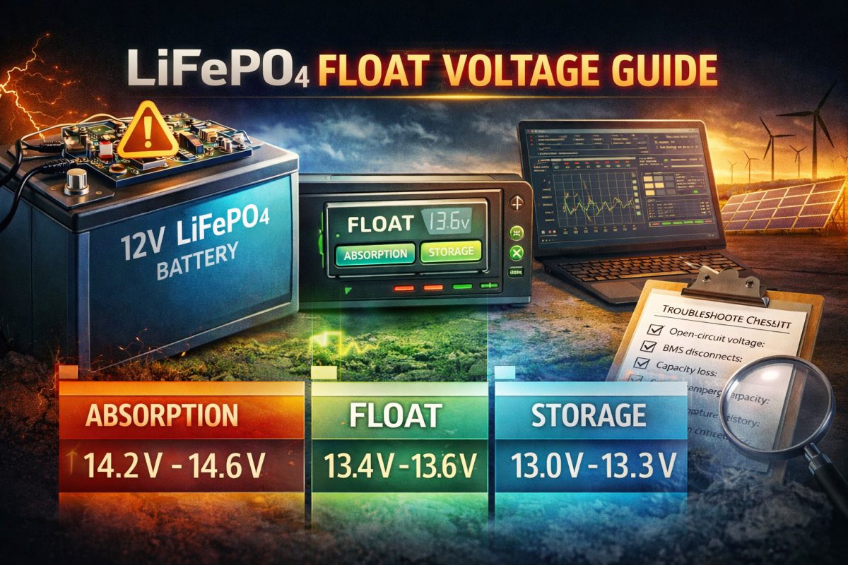
Bulk/absorption (full charge): ~14.2–14.6 V (≈3.55–3.65 V/cell).
-
Typical float (if used): ~13.4–13.6 V (≈3.35–3.40 V/cell).
-
Storage / long idle: 13.0–13.3 V (≈3.25–3.33 V/cell).
-
-
24 V nominal (8 cells in series): scale the above by two (absorption ≈28.4–29.2 V; float ≈27.2–27.4 V; storage ≈26.0–26.6 V).
-
48 V nominal (16 cells in series): scale similarly (absorption ≈56.8–58.4 V; float ≈54.4–54.8 V; storage ≈52.0–53.2 V).
Two operational notes: (1) “full” LFP voltage range is narrow — small voltage differences imply significant state-of-charge changes — so set your thresholds precisely; (2) many manufacturers publish slightly different numbers; prefer the cell datasheet and conservative system settings when in doubt.
Why float settings matter — tradeoffs and failure modes
-
Continuous float at high voltage stresses cells: keeping LFP cells at the upper end of voltage increases calendar ageing and accelerates cycle-life loss. A too-high float (or poorly tuned absorption) produces mild but cumulative capacity fade.
-
Too low float increases recharge cycles: an aggressively low float or storage voltage can increase the number of recharge cycles for systems that see daily partial discharge, which may also shorten overall life if the depth of discharge profile changes.
-
BMS interactions: BMS devices that open contactors at full-charge make continuous float irrelevant; for such systems treat float as a restart threshold (i.e., the voltage at which the charger will re-enable charging after slight self-discharge).
Practical charging profiles and configuration recipes
-
Grid-tied or hybrid ESS with continuous availability: use an absorption point near 14.2–14.4 V (12 V system) with float set at 13.4–13.6 V as a soft hold for readiness. Keep float timeouts or periodic top-ups instead of continuous high-float.
-
Off-grid systems where longevity is paramount: charge to absorption then remove float entirely, or set a low float (≈13.2–13.4 V) and rely on scheduled top-ups; enforce a periodic balancing cycle.
-
Backup UPS where immediate high state of charge is required: a modest float around 13.6 V gives readiness but only when the BMS and thermal environment are controlled. Monitor long-term capacity and consider cycling tests to validate aging.
Storage and seasonal lay-up
For long-term storage (weeks to months): store at 30–60% SOC (roughly 13.0–13.3 V for a 12 V LFP pack). This reduces stress and slows calendar ageing. Before returning stored packs to service, perform a controlled charge and cell balancing cycle and verify per-cell voltages. For fleets, keep records of storage voltages and ambient temperatures — both materially affect aging rates.
BMS, telemetry, and process controls — make the float setting visible
-
Log float-time, float voltage, and the number of float cycles in your fleet telemetry. Trends are a much stronger predictor of trouble than single readings.
-
Use BMS alarms to flag extended float durations or repeated re-enable events (charger re-engages dozens of times per day). This indicates either a parasitic drain or an incorrectly low float threshold.
-
Automate periodic balancing: if you must use float for availability, schedule active balancing windows to avoid persistent cell voltage divergence.
Troubleshooting checklist (fast)
-
Measure open-circuit pack voltage after 30 minutes of rest. Compare per-cell voltages.
-
If float is high (>13.7 V on a 12 V pack) and cells are warm, reduce float and inspect charger firmware.
-
If BMS repeatedly opens contactors at full charge, log the event time and correlate with charger telemetry — adjust absorption duration or float behavior accordingly.
-
For surprise capacity loss, check long-term float exposure history before replacing cells.
Conclusion — tune float to the mission, not to habit
Float is not a “set and forget” parameter for LiFePO₄ systems. The right approach balances readiness with longevity: use absorption to reach full charge, minimize continuous high float, rely on BMS-aware top-ups, and instrument the system so float becomes a controllable operational variable — not an accidental source of wear. Conservative float values, routine balancing, and telemetry-driven maintenance will extend pack life and reduce unscheduled interventions across fleets and installations.
Key recommendations in this guide are drawn from practical LFP operating norms and manufacturer guidance; use your cell datasheet and system BMS specification as the final authority when selecting voltages and thresholds.


